-
-
- All Modular
-
-
 All Modular Brands
- 1010 Music
- 2hp
- 4ms
- Ali Modular
- ALM Busy Circuits
- Ampersand Ampersand
- Antimatter Audio
- Bastl Instruments
- Befaco
- Boredbrain
- Buchla USA
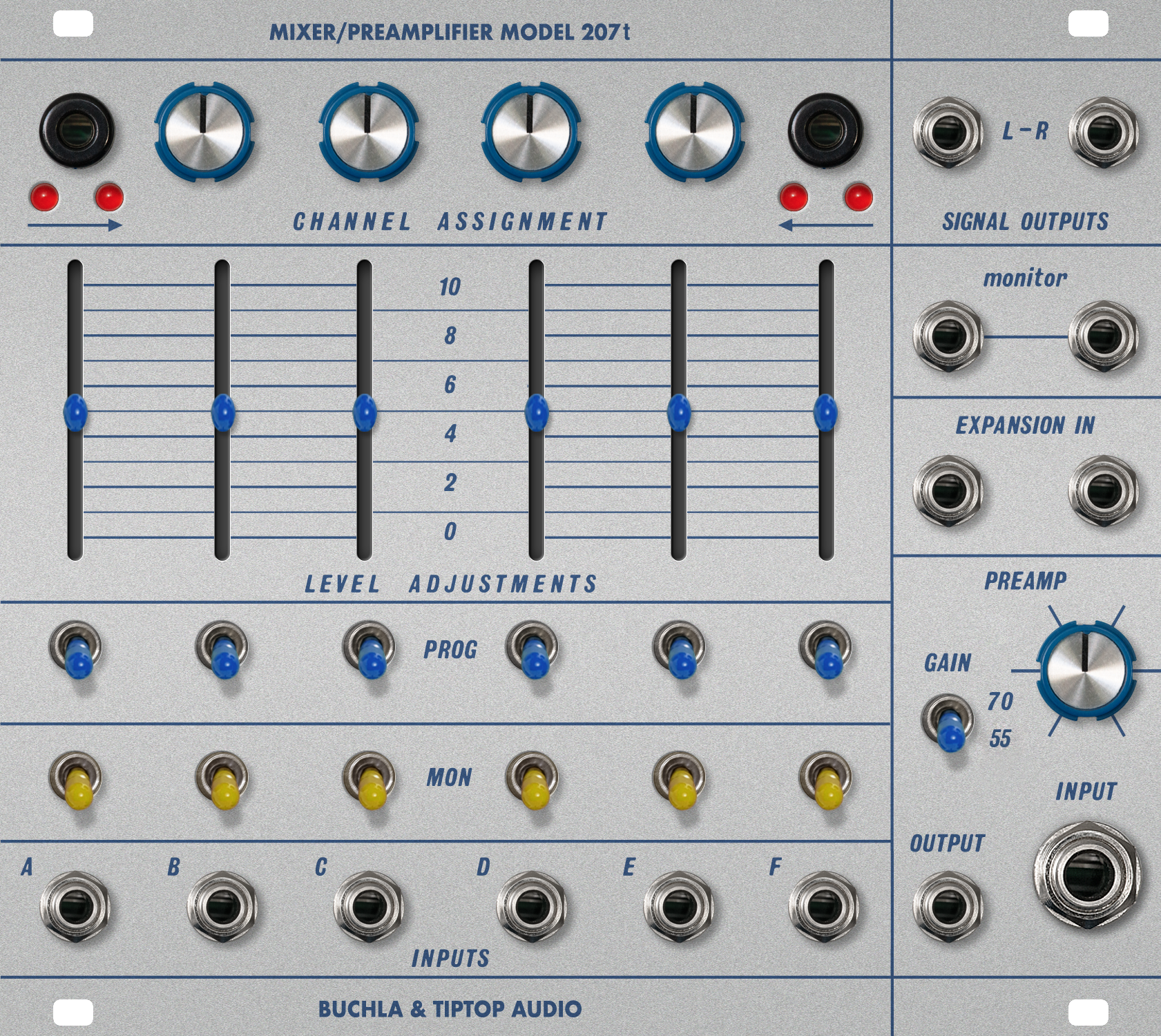
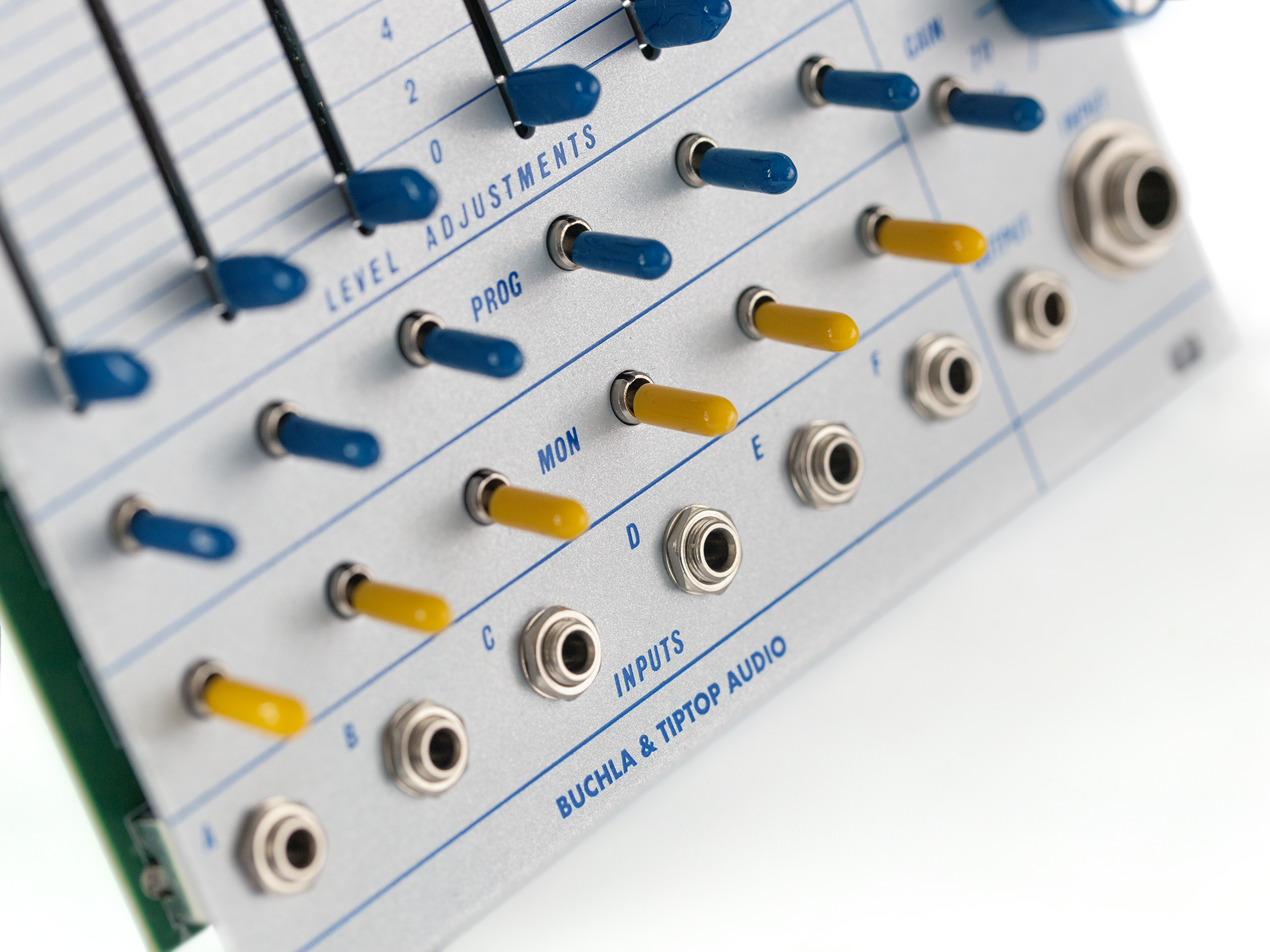
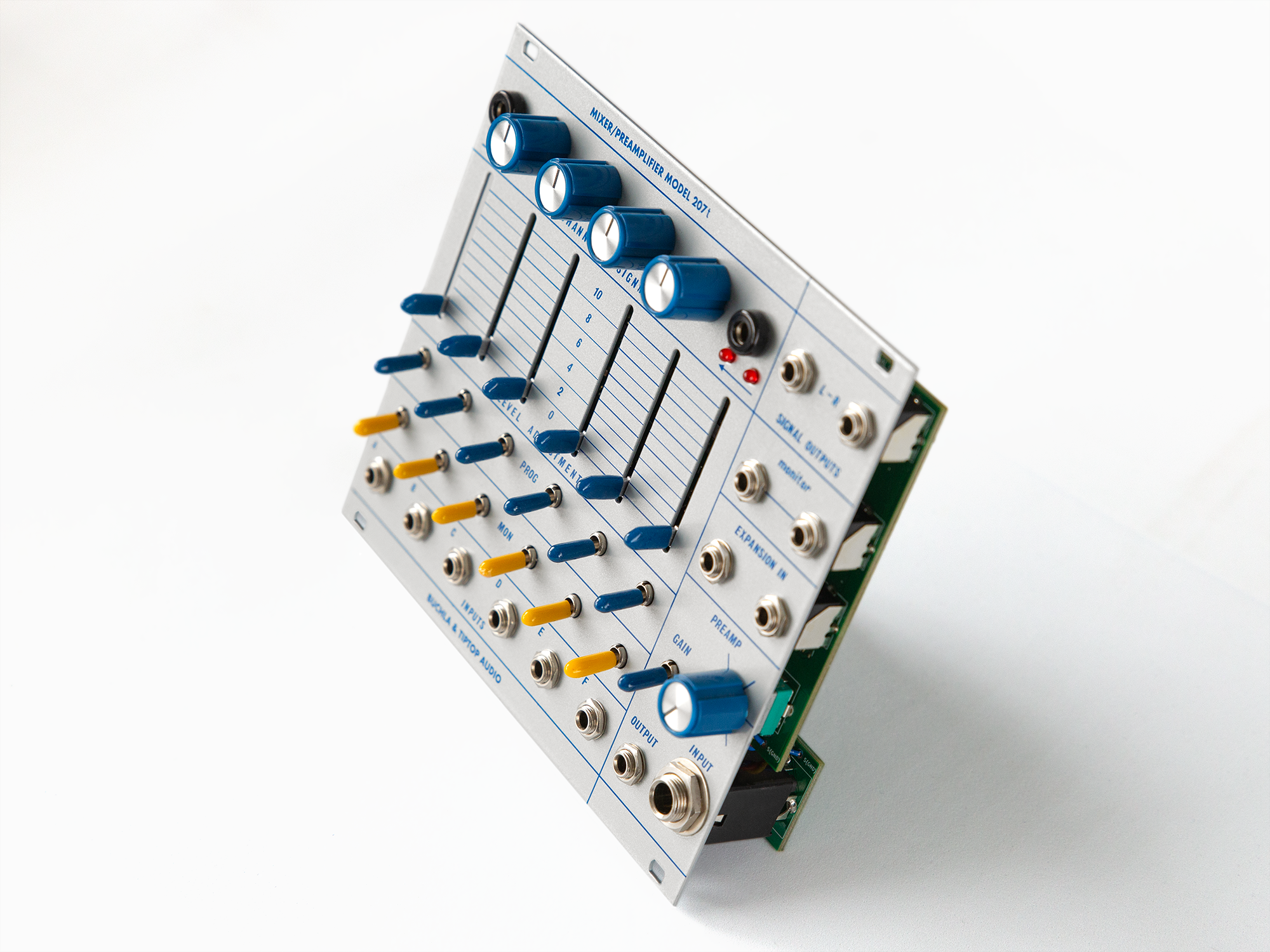
- Buchla & Tiptop Audio
- DivKid
- EarthQuaker Devices
- Elektrofon
- Empress Effects
- Endorphin.es
- Erica Synths
- Expert Sleepers
- Exploding Shed
- Forge TME
- Hexinverter Électronique
- Industrial Music Electronics
- Instruo
- Intellijel
- Knobula
- KOMA Elektronik
- LZX Industries
- Make Noise
- Malekko Heavy Industry
- Manifold Research Centre
- Modbap Modular
- Molten Modular
- Moog
- Mordax
- Mosaic
- Noise Engineering
- Ohm Force
- OXI Instruments
- Patching Panda
- Qu-Bit Electronix
- Roland
- Rossum Electro-Music
- RYK Modular
- Schlappi Engineering
- SOMA Laboratory
- soundmachines
- Squarp Instruments
- Steady State Fate
- This Is Not Rocket Science
- Tiptop Audio
- Toppobrillo
- Venus Instruments
- Vostok
- vpme.de
- Weston Precision Audio
- Winter Modular
- Winter Plankton
- WMD
- Worng Electronics
- XAOC Devices
-
- Full Voice
- ART Compatible
- Filter
- Drum Module
- VCA
- Touch & Control
- Effect
- Mixer
- MIDI & Computer Interface
- Clock Utility
- Dual/Stereo, Quad, Octa, Etc
- Oscilloscope
- Video Synthesis
- Expander
- 1U Tile Module
- DIY
- Modular System
- Modular Accessory
- Alternate Panel
- Used Modules
- Used Cases & Parts
-
 Synthesizers
-
 Controllers
-
 Drum Machines
-
 Sequencers
-
 Samplers
-
 Soundmakers
-
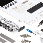 DIY
DIY
-
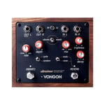 Effects
-
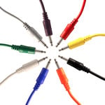 Cables
-
 Audio/MIDI
-
 Video
Video
-
 Music/Media/Gifts
-
 Accessories
-
 Used
Used
-
 Vintage
-
 DEALS
DEALS
-
Control Voltage
Close -
 Modular
-
 Synthesizers
-
 Controllers
-
 Drum Machines
-
 Sequencers
-
 Samplers
-
 Soundmakers
-
 DIY
DIY
-
 Effects
-
 Cables
-
 Audio/MIDI
-
 Video
Video
-
 Music/Media/Gifts
-
 Accessories
-
 Used
Used
-
 Vintage
-
 DEALS
DEALS
- Modular Brands
- 1010 Music
- 2hp
- 4ms
- Ali Modular
- ALM Busy Circuits
- Ampersand Ampersand
- Antimatter Audio
- Bastl Instruments
- Befaco
- Boredbrain
- Buchla USA
- Buchla & Tiptop Audio
- DivKid
- EarthQuaker Devices
- Elektrofon
- Empress Effects
- Endorphin.es
- Erica Synths
- Expert Sleepers
- Exploding Shed
- Forge TME
- Hexinverter Électronique
- Industrial Music Electronics
- Instruo
- Intellijel
- Knobula
- KOMA Elektronik
- LZX Industries
- Make Noise
- Malekko Heavy Industry
- Manifold Research Centre
- Modbap Modular
- Molten Modular
- Moog
- Mordax
- Mosaic
- Noise Engineering
- Ohm Force
- OXI Instruments
- Patching Panda
- Qu-Bit Electronix
- Roland
- Rossum Electro-Music
- RYK Modular
- Schlappi Engineering
- SOMA Laboratory
- soundmachines
- Squarp Instruments
- Steady State Fate
- This Is Not Rocket Science
- Tiptop Audio
- Toppobrillo
- Venus Instruments
- Vostok
- vpme.de
- Weston Precision Audio
- Winter Modular
- Winter Plankton
- WMD
- Worng Electronics
- XAOC Devices
- Sound Source
- Full Voice
- ART Compatible
- Filter
- Drum Module
- VCA
- Sequencer
- Touch & Control
- Modulation Source
- Modifier
- Effect
- Mixer
- Input & Output
- MIDI & Computer Interface
- Clock Utility
- Utility
- Dual/Stereo, Quad, Octa, Etc
- Oscilloscope
- Video Synthesis
- Expander
- 1U Tile Module
- DIY
- Modular System
- Modular Accessory
- Alternate Panel
- Used Modules
- Cases & Power
- Patch Cables
- Used Cases & Parts
-
- ⚡️ On Sale ⚡️
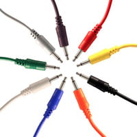
 All Patch Cables