All Modular Brands
 All Patch Cables
 Synthesizers
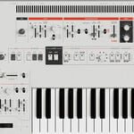
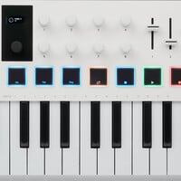
 Controllers
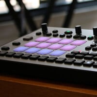
 Drum Machines
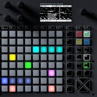
 Sequencers
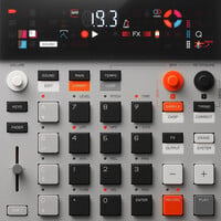
 Samplers
 Soundmakers
 DIY
DIY
 Effects
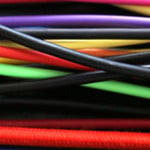
 Cables
 Audio/MIDI
 Video
Video
 Music/Media/Gifts
 Accessories
 Used
Used
 Vintage
 DEALS
DEALS
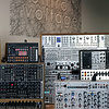
 Modular
 Synthesizers
 Controllers
 Drum Machines
 Sequencers
 Samplers
 Soundmakers
 DIY
DIY
 Effects
 Cables
 Audio/MIDI
 Video
Video
 Music/Media/Gifts
 Accessories
 Used
Used
 Vintage
 DEALS
DEALS

LFO Variables & Destinations
As we’ve learned, modulation is the key to interesting and organic sounds that evolve over time. Some of the most interesting synthesizers are those that include a large number of LFOs that can be routed to a plethora of destinations.
We also learned that LFOs can directly control parameters of audio path modules, for instance, when a LFO modulates the cutoff frequency of a filter - this is called first order modulation. They can also control parameters of other control path modules, for instance, when an LFO modulates the attack time of an envelope - this is called second order modulation.
When using LFOs as control signals, there are many variables to consider. Some of this may be recap from Basic Synth 4: LFO's, Envelopes & Random Voltage, but we’re going to dive a little deeper into what makes LFOs so powerful and common destinations to route them to.
Typical LFO Variables:
- Waveform: The waveform of the LFO determines the shape at which modulation occurs. Similar to audio oscillators, the classic waveforms were often used for LFOs - sine, triangle, sawtooth/ramp, square, and pulse waves. A common misconception is that random voltage and smooth random voltage are LFO waveforms. This is not true. In the same way that a noise generator is not an oscillator, random voltage is not a LFO waveform.
- Frequency: Remember - LFOs are just subsonic oscillators, so the same rules apply! The frequency of the LFO, measured in hertz (Hz), determines the rate at which modulation occurs. Pro tip - vibrato and tremolo are achieved at around 3Hz-7Hz
- Polarity: Going back to Basic Synth 0: Control Voltage, we learned that voltage can be unipolar positive (positive voltage fluctuates above 0V), unipolar negative (negative voltage fluctuates below 0V), or bipolar (positive and negative voltage fluctuations cross 0V). It’s important to note that modulation is also determined by the CV input range of the parameter. Most analog CV inputs can accept bipolar voltage (e.g. input range of ±5V), but some digital CV inputs can only accept unipolar positive voltage (e.g. input range of 0V-5V). In most cases, modulation is added to the parameter’s knob position. That being said, if a bipolar LFO is used to modulate a unipolar positive CV input, the negative portion of the LFO will be clipped at 0V. In order for the full LFO signal to be accepted by the unipolar positive CV input, the LFO must be offset to a fully positive signal. Similarly, if a unipolar LFO is used to modulate a bipolar CV input, modulation will only occur on one side of the parameter’s knob position. Offsetting the unipolar LFO to be bipolar will allow modulation to occur on both sides of the parameter’s knob position.
- Amplitude: The amplitude of the LFO determines the depth of modulation. The higher the amplitude, the more influence the signal will have over the destination parameter. For more subtle modulations like pitch vibrato in a string patch, we often patch LFOs through an attenuator to limit the amplitude of the signal. In keyboard synthesizers, the modulation wheel often defaults as a LFO attenuator.
- Phase: Phase is an interesting topic. I like to think of it as offsetting the signal within the time domain while maintaining the same frequency. The best way to think about this is in a quadrature LFO setup. For instance, four separate LFOs can all be set to the same frequency, but be 90° out of phase from one another. For instance, LFO 1 starts its cycle and once its 90° through its cycle, LFO 2 starts its cycle. Once LFO 2 is 90° through its cycle, LFO 3 starts its cycle. Once LFO 3 is 90° through its cycle, LFO 4 starts its cycle. Once LFO 4 is 90° through its cycle, LFO 1’s cycle resets, completing a 360° circle of modulation.
- Reset: A common feature of LFOs is the ability to reset the waveform cycle with the presence of a rising-edge signal (like a gate or trigger signal) at its reset input. Often it's helpful to patch a keyboard’s gate output to the LFO’s reset input, which forces the LFO to reset with every key press. If, for example, the LFO is patched to modulate the cutoff frequency of the filter, this ensures that the LFO won't be mid-cycle when the VCA is opened by the envelope generator.
- Sync: In LFO world, sync can mean two different things. If we think about LFOs like we think about oscillators, then we know that soft synchronization and hard synchronization are both possible. If we think about digital tap tempo LFOs, then we know that a LFO can be synchronized to an external clock source. This means that no matter what the clock rate is, a full cycle of a LFO will exist between any two successive clock pulses.
- Delay/Fade Time: Some LFOs have dedicated linear envelopes and VCAs included in their architecture allowing the LFO to fade in over time. This is great for faded-in vibrato and faded-in tremolo patches.
- Architecture: Analog LFOs will always be smoother than digital LFOs for the same reasons that analog oscillators are smoother than wavetable oscillators. In the digital world, we really care about the amount of resolution a waveform has so that we don’t experience steppiness in our modulation. For instance, low resolution modulation on the pitch of an oscillator is very noticeable and often unwanted. That being said, most modern digital modulation sources have a high enough resolution to where steppiness is not perceived except for maybe at very slow rates.
- Destination: The LFO destination is the parameter within the system that the LFO is moduating, which could literally be anything you want! *Sigh* the beauty of modular synthesis.
Typical LFO Destinations:
- Pitch Vibrato: Bipolar sine LFO to FM input on oscillator
- Octave Pitch Trill: Unipolar positive square LFO to FM input on oscillator
- Syncopated Octave Pitch Trill: Unipolar positive pulse LFO to FM input on oscillator
- “Red Alert”: Unipolar positive ramp LFO to FM input on oscillator
- VCA Tremolo: Unipolar positive sine LFO to AM input on VCA
- VCA On/Off: Unipolar positive square LFO to AM input on VCA
- PWM Chorusing: Bipolar LFO to PWM input on oscillator
- Filter Wah-Wah: Unipolar LFO to FM input on low pass filter